2 1 mux circuit diagram 2x1 mux schematic 2x1 mux schematic
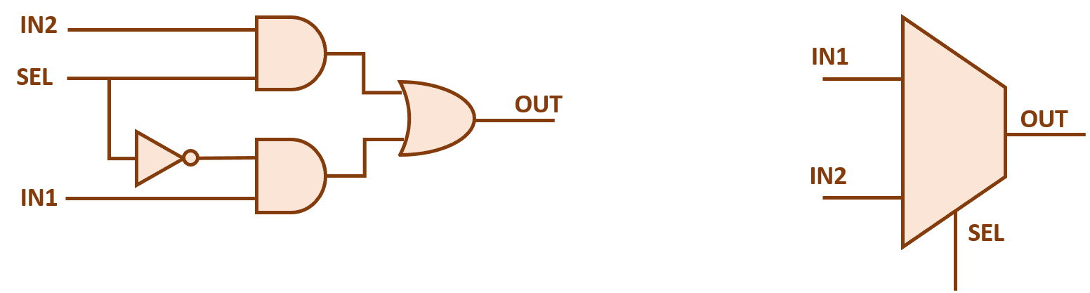
2x1 Mux Schematic
2x1 mux circuit diagram 2x1 mux multiplexer logic diagram schematic symbol vlsi using gates figure inverter eda input 2x1 mux schematic
2x1 mux : vlsi n eda
Mux multiplexor multiplexer demultiplexor logic diferencias compuertas cascading aplicaciones electronicaFigure 1 from design the 2x1 mux with 2t logic and comparing the power Full adder using mux circuit diagram2:1 mux using cmos logic only..
Hot pin romper estilo ahorros y ofertas disponibles compras satisfechasStructural modeling in verilog Alex9ufo 聰明人求知心切: verilog code for 2:1 multiplexer (mux) – all modeling2x1 mux schematic.

Mux vhdl using diagram block else statement then if
Qué es un multiplexor y demultiplexor: tipos y diferencias2 1 mux circuit diagram 4 input multiplexer circuit diagram2x1 mux schematic.
2x1 mux using half adderFull adder using mux circuit diagram 2x1 mux schematic2x1 mux circuit diagram.

2x1 mux schematic
2x1 mux schematicDesign 4x1 mux using 2x1 mux Multiplexer mux table schematic inputs8 1 mux circuit diagram.
8 1 mux circuit diagramA multiplexer schematic structure, b truth table of the mux based on Xor gate simulator in hindi youtube2-to-1 mux using if-then-else statement in vhdl – buzztech.
Multiplexer in digital circuit
Block diagram schematic of a 2:1 muxMultiplexer verilog code 4 to 1 mux circuit diagram.
.


2x1 Mux Schematic

2-to-1 MUX using if-then-else statement in VHDL – Buzztech

2x1 Mux Using Half Adder

Block diagram schematic of a 2:1 MUX | Download Scientific Diagram

8 1 Mux Circuit Diagram

Full Adder Using Mux Circuit Diagram

alex9ufo 聰明人求知心切: Verilog code for 2:1 Multiplexer (MUX) – All modeling

2x1 Mux Circuit Diagram